

본문
Steam Accumulator
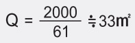
- Scenario A: If the boiler load is gradually adjusted, the amount of stored steam will decrease, but the boiler capacity must increase to 18T/H.
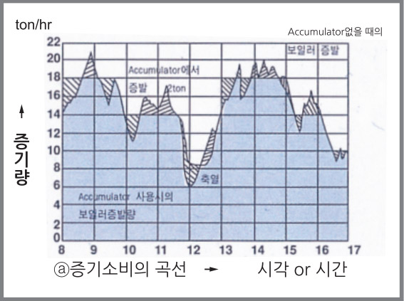
- Scenario B: If the boiler operates at a constant average evaporation rate, the accumulator will need to store more steam. However, the boiler capacity can be reduced to 15T/H to meet the demand.
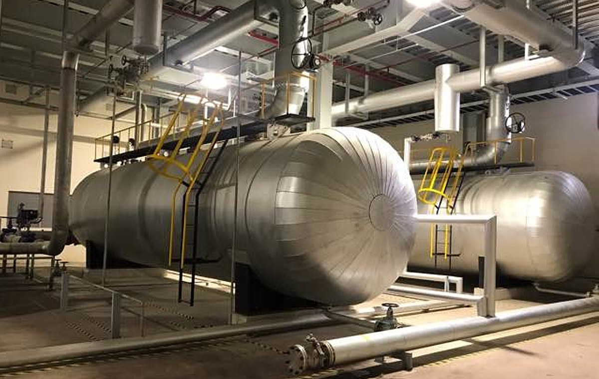
Let’s assume the maximum steam accumulation required is 2 tons, as determined from the steam consumption curve.
If the maximum pressure of the accumulator is 16 kg/cm²(g) and the plant's operating pressure is 7 kg/cm²(g), the heat storage chart gives a value of 61 at the intersection of these two pressures.
※ Note: The size of the accumulator is determined by the magnitude of steam load fluctuations, not directly by the boiler size.
Increased Boiler Capacity
Supports higher production and improved product quality.
Energy Savings
Allows the boiler to remain idle during nights, holidays, or early mornings.
Extended Boiler Lifespan
Reduces wear and tear on the boiler by maintaining consistent operation.
Emergency Steam Supply
Ensures steam availability even during boiler failures or power outages.
Reduced Emissions
Minimizes soot emissions and lowers NOx levels.
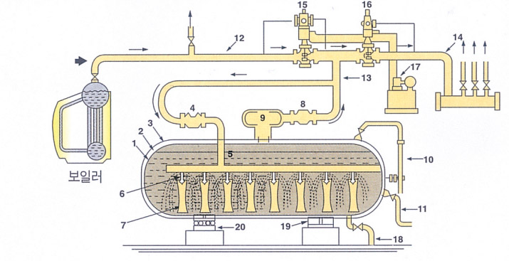
- 1. Accumulator Body
- 2. Insulation Material
- 3. Insulation Casing
- 4. Inlet Steam Stop Valve
- 5. Steam Distribution Pipe
- 6. Steam Nozzle
- 7. Circulation Pipe
- 8. Outlet Steam Stop Valve
- 9. Steam Separator
- 10. Water Level Gauge
- 11. Feedwater Pipe
- 12. High-Pressure Steam Pipe
- 13. Connection Steam Pipe
- 14. Low-Pressure Steam Pipe
- 15. High-Pressure AVA Valve
- 16. Low-Pressure AVA Valve
- 17. Hydraulic Pump
- 18. Blow Valve
- 19. Fixed Support
- 20. Sliding Support
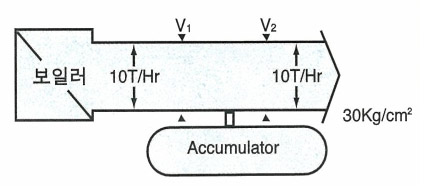
1.When steam consumption matches boiler production:
No steam is stored or released by the accumulator.
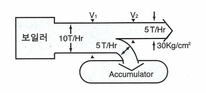
2.When steam consumption decreases:
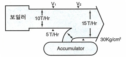
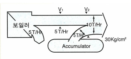
3.When steam consumption increases:
Steam stored in the accumulator is released to meet demand.
4.When high-pressure steam demand rises and low-pressure steam is insufficient:
The accumulator supplies low-pressure steam.
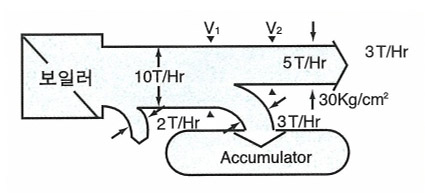
5.When both high- and low-pressure steam demands decrease:
Steam is stored in the accumulator.
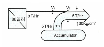
6.In case of boiler failure or power outage:
The accumulator provides emergency steam supply.
Automatic control valves (V1 and V2) continuously and efficiently manage the accumulator, ensuring the boiler operates at maximum efficiency and economic performance.
 Drag screen right and left
| Accumulator | 7 | 8 | 9 | 10 | 12 | 14 | 15 | 16 | 17 | 20 | 22 | 24 | |
| Accumulator Min. pressure kg/cfg |
2 | 66 | 84 | 81 | 87 | 99 | 110 | 115 | 119 | 127 | 136 | 143 | 149 |
| 3 | 48 | 57 | 65 | 71 | 84 | 95 | 99 | 104 | 113 | 121 | 127 | 134 | |
| 4 | 33 | 42 | 50 | 57 | 69 | 81 | 86 | 91 | 100 | 108 | 116 | 122 | |
| 5 | 22 | 61 | 39 | 46 | 59 | 70 | 76 | 80 | 90 | 97 | 106 | 112 | |
| 6 | 28 | 34 | 47 | 59 | 65 | 69 | 78 | 87 | 95 | 102 | |||
| 7 | 38 | 50 | 56 | 51 | 70 | 78 | 86 | 92 | |||||
| 8 | 43 | 47 | 53 | 63 | 71 | 78 | 84 | ||||||
| 9 | 44 | 55 | 63 | 70 | 76 | ||||||||
| 10 | 47 | 56 | 64 | 70 | |||||||||
| 11 | 49 | 57 | 63 | ||||||||||
| 12 | 43 | 50 | 56 |
The diagram displays the primary pressure transversely and the secondary pressure longitudinally.
If the pressure drops from 10kg/㎤g to 5kg/㎤g, you can get a value of 46kg/㎤ by descending vertically from 10 on the upper horizontal axis and reading the point where it meets 5kg/㎤g on the left vertical axis.
This is the amount of steam that can accumulate per cubic meter of thermal water.